Chassis Jumper Connection
Connect the cables removed from the motherboard to this device to retain the functionality of the chassis power button and reset button.
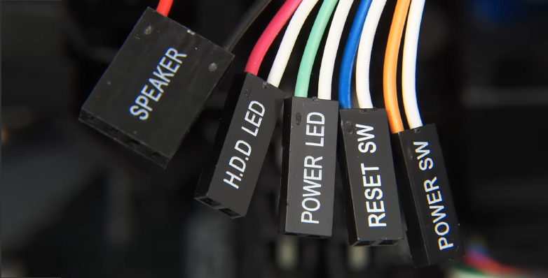
Understanding Jumpers
Please refer to the paper motherboard manual included with your device or the electronic version on the official website to locate the sections labeled POWER SW , RESET SW , and POWER LED .
| Illustration | Label | Function | Notes |
|---|---|---|---|
 | POWER SW | Power on/off | None |
 | RESET SW | Reset | None |
 | POWER LED (+-) | Power indicator | *Polarity sensitive |
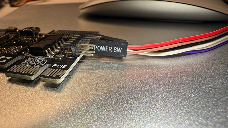
Chassis Power Button Connection
Connect the chassis power button cable to this device to retain the power on/off functionality of the chassis power button.
- Locate the
POWER SWjumper connecting the chassis to the motherboard and remove it from the motherboard. - Insert the removed
POWER SWjumper from the chassis into thePOWER SWslot on this device.
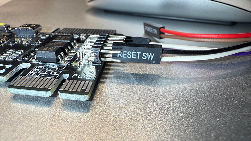
Reset Jumper Connection
Connect the chassis reset cable to this device to retain the reset functionality of the chassis reset button.
- Locate the
RESET SWjumper connecting the chassis to the motherboard and remove it from the motherboard. - Insert the removed
RESET SWjumper from the chassis into theRESET SWslot on this device.
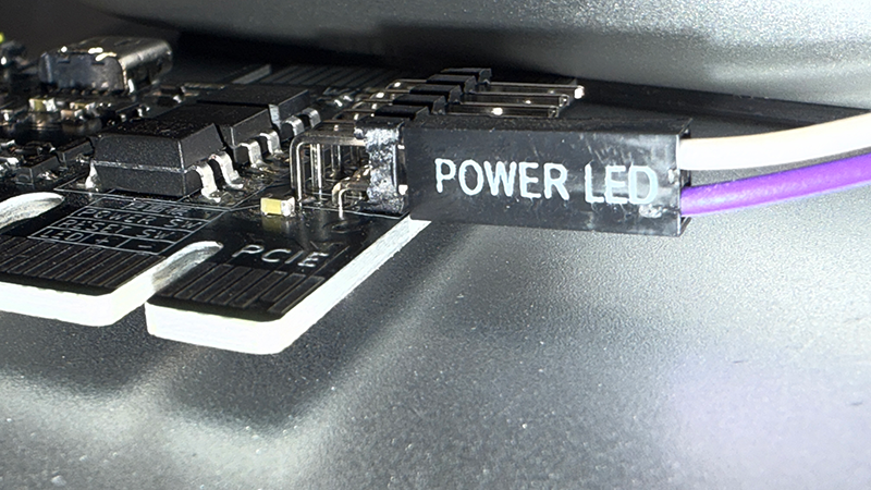
Power Indicator Jumper Connection
Warning
- If you are not using an external Type-C power supply, do not connect this jumper!!!
- This jumper is polarity-sensitive. If the power status is not recognized, swap the two wires and reconnect them to the motherboard.
- Locate the
POWER LEDjumper connecting the chassis to the motherboard and remove it from the motherboard. - Insert the removed chassis jumper into the
POWER LEDslot on this device.
Copyright
License under:Attribution 4.0 International (CC-BY-4.0)